Lab 6
Introduction
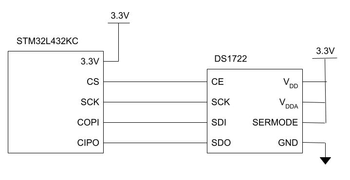
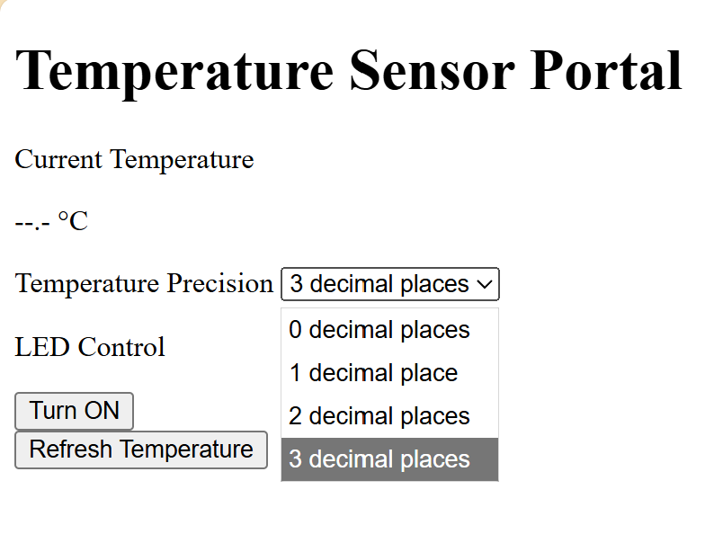
The goal of Lab 6 was to read a temperature using the SPI (serial peripheral interface) communication protocol. The resolution of this reading (as well as an on-board) LED were controlled with a web server using HTTP (hypertext transfer protocol), and the temperature is also displayed on the web server.
Schematic
The circuit diagram is as follows:
Code:
/**
    Main Header: Contains general defines and selected portions of CMSIS files
    @file main.h
    @author Madeleine Kan, adapted from Josh Brake
    @version 10/27/25
*/

#ifndef MAIN_H
#define MAIN_H

#include "STM32L432KC.h"

#define LED_PIN PA6 // LED pin for blinking on Port A pin 9
#define BUFF_LEN 32

char* webpageStart = "<!DOCTYPE html><html><head><title>Madeleine Kan E155 Web Server Webpage</title>\
    <meta name=\"viewport\" content=\"width=device-width, initial-scale=1.0\">\
    </head>\
    <body><h1>E155 Web Server Demo Webpage</h1>";
char* ledStr = "<p>LED Control:</p><form action=\"ledon\"><input type=\"submit\" value=\"Turn the LED on!\"></form>\
    <form action=\"ledoff\"><input type=\"submit\" value=\"Turn the LED off!\"></form>";
char* resolutionStr = "<p>Resolution Control:</p><form action=\"8\"><input type=\"submit\" value=\"8 bits\"></form>\
      <form action=\"9\"><input type=\"submit\" value=\"9 bits\"></form>\
      <form action=\"10\"><input type=\"submit\" value=\"10 bits\"></form>\
      <form action=\"11\"><input type=\"submit\" value=\"11 bits\"></form>\
      <form action=\"12\"><input type=\"submit\" value=\"12 bits\"></form>";
char* webpageEnd   = "</body></html>";

#endif // MAIN_H
/*
File: lab6_mk.c
Author: Madeleine Kan, adopted from Josh Brake
Email: mkane@hmc.edu
Date: 10/27/25
*/
#include <string.h>
#include <stdlib.h>
#include <stdio.h>
#include "main.h"
#include "ds1722.h"
/////////////////////////////////////////////////////////////////
// Provided Constants and Functions
/////////////////////////////////////////////////////////////////
//determines whether a given character sequence is in a char array request, returning 1 if present, -1 if not present
int inString(char request[], char des[]) {
if (strstr(request, des) != NULL) {return 1;}
return -1;
}
int updateLEDStatus(char request[])
{
int led_status = 0;
// The request has been received. now process to determine whether to turn the LED on or off
if (inString(request, "ledoff")==1) {
digitalWrite(LED_PIN, PIO_LOW);
printf("off \n");
led_status = 0;
}
else if (inString(request, "ledon")==1) {
digitalWrite(LED_PIN, PIO_HIGH);
printf("on \n");
led_status = 1;
}
return led_status;
}
int updateResolution(char request[]){
int resolution = 0;
// The request has been received. now process the resolution
if (inString(request, "8")==1) {
printf("resolution = 8 \n");
resolution = 8;
} else if (inString(request, "9")==1) {
printf("resolution = 9 \n");
resolution = 9;
} else if (inString(request, "10")==1) {
printf("resolution = 10 \n");
resolution = 10;
} else if (inString(request, "11")==1) {
printf("resolution = 11 \n");
resolution = 11;
} else if (inString(request, "12")==1) {
printf("resolution = 12 \n");
resolution = 12;
}
return resolution;
}
/////////////////////////////////////////////////////////////////
// Solution Functions
/////////////////////////////////////////////////////////////////
//// internet ISO
int main(void) {
configureFlash();
configureClock();
gpioEnable(GPIO_PORT_A);
gpioEnable(GPIO_PORT_B);
gpioEnable(GPIO_PORT_C);
pinMode(LED_PIN, GPIO_OUTPUT);
digitalWrite(LED_PIN, PIO_LOW);
//RCC->APB2ENR |= (RCC_APB2ENR_TIM15EN);
//initTIM(TIM15);
RCC->APB1ENR1 |= (RCC_APB1ENR1_TIM2EN);
initTIM(TIM2);
USART_TypeDef * USART = initUSART(USART1_ID, 125000);
// initialize SPI with (80 / 32 = ) 2.5 MHz baudrate, cpol=0, cpha=1
initSPI(0b100, 0, 1);
volatile char config;
// printf("config settings: %x \n", config);
volatile float temp;
while(1) {
/* Wait for ESP8266 to send a request.
Requests take the form of '/REQ:<tag>\n', with TAG begin <= 10 characters.
Therefore the request[] array must be able to contain 18 characters.
*/
// Receive web request from the ESP
char request[BUFF_LEN] = " "; // initialize to known value
int charIndex = 0;
// Keep going until you get end of line character
while(inString(request, "\n") == -1) {
// Wait for a complete request to be transmitted before processing
while(!(USART->ISR & USART_ISR_RXNE));
request[charIndex++] = readChar(USART);
}
// Update strings with current LED state and resolution
int led_status = updateLEDStatus(request);
int resolution = updateResolution(request);
// configure temp sensor
config = configureTempSensor(resolution);
// SPI code here for reading temperature
temp = readTemp(resolution);
char ledStatusStr[20];
char tempStatusStr[25]; // temp is double is 64 bits, or 8 bytes
char resolutionStatusStr[25];
sprintf(tempStatusStr, "temp: %.4f deg C\n", temp);
sprintf(resolutionStatusStr, "resolution = %d bits", resolution);
//printf("%f", temp);
//printf(tempStatusStr);
if (led_status == 1){
sprintf(ledStatusStr,"LED is on!");
} else if (led_status == 0){
sprintf(ledStatusStr,"LED is off!");
}
// finally, transmit the webpage over UART
sendString(USART, webpageStart); // webpage header code
sendString(USART, ledStr); // button for controlling LED
sendString(USART, resolutionStr); // buttons for controlling resolution
sendString(USART, "<h2>LED Status</h2>");
sendString(USART, "<p>");
sendString(USART, ledStatusStr);
sendString(USART, "</p>");
sendString(USART, "<h2>Temperature</h2>");
sendString(USART, "<p>");
sendString(USART, tempStatusStr);
sendString(USART, "</p>");
sendString(USART, "<p>");
sendString(USART, resolutionStatusStr);
sendString(USART, "</p>");
sendString(USART, webpageEnd);
}
}// DS1722.h
// Madeleine Kan
// mkan@hmc.edu
// 27 October 2025
// Header file for DS1722 temperature sensor
#ifndef DS1722_H
#define DS1722_H
#include "STM32L432KC.h"
volatile char configureTempSensor(int resolution);
volatile float readTemp(int resolution);
#endif// DS1722.c
// Madeleine Kan
// mkan@hmc.edu
// 27 October 2025
// Functionality for DS1722 temperature sensor
#include "STM32L432KC.h"
// configures and enables temperature sensor for 8-12 bits of resolution
// then, reads back configuration
// returns int corresponding to configuration settingss
volatile char configureTempSensor(int resolution){
// first 4 bits of config status register will always be 1110 since we don't want one shot mode
// last 4 bits will be 3'bresolution_SD
// since we are enabling the temp sensor, we are writing 0 to SD
volatile char result1;
volatile char result2;
volatile char config;
int a = 0;
digitalWrite(CS, PIO_HIGH);
// config write address
spiSendReceive(0x80);
switch(resolution){
case 8:
result2 = spiSendReceive(0xE0);
break;
case 9:
result2 = spiSendReceive(0xE2);
break;
case 10:
result2 = spiSendReceive(0xE4);
break;
case 11:
result2 = spiSendReceive(0xE6);
break;
case 12:
result2 = spiSendReceive(0xE8);
break;
default:
break;
}
digitalWrite(CS, PIO_LOW);
digitalWrite(CS, PIO_HIGH);
spiSendReceive(0x0);
config = spiSendReceive(0x00);
digitalWrite(CS, PIO_LOW);
printf("old settings: %x \n", result1);
printf("other settings: %x \n", result2);
printf("new settings: %x \n", config);
return config;
}
volatile float readTemp(int resolution){
volatile int16_t temp_MSB = 0;
volatile int16_t temp_LSB = 0;
volatile float frac_temp_LSB = 0;
volatile float temp_raw = 0;
volatile float temp = 0;
int isPositive = 0;
digitalWrite(CS, PIO_HIGH);
spiSendReceive(0x02);
temp_MSB = (uint16_t) spiSendReceive(0x00);
spiSendReceive(0x00);
digitalWrite(CS, PIO_LOW);
digitalWrite(CS, PIO_HIGH);
spiSendReceive(0x01);
temp_LSB = (uint16_t) spiSendReceive(0x00);
spiSendReceive(0x00);
digitalWrite(CS, PIO_LOW);
temp_raw = ((temp_MSB << 8) | temp_LSB);
temp = temp_raw/256;
printf("temp LSB: %x \n", temp_LSB);
printf("temp MSB: %x \n", temp_MSB);
printf("temp: % .4f\n", temp);
return temp;
}And the SPI code, from the interrupt-tutorial solution branch:
// STM32L432KC_SPI.h
// Header for SPI functions

#ifndef STM32L4_SPI_H
#define STM32L4_SPI_H

#include <stdint.h>
#include <stm32l432xx.h>

#define SCK PB3
#define CIPO PB4
#define COPI PB5
#define CS PB1

///////////////////////////////////////////////////////////////////////////////
// Function prototypes
///////////////////////////////////////////////////////////////////////////////

/* Enables the SPI peripheral and intializes its clock speed (baud rate), polarity, and phase.
 *    -- br: (0b000 - 0b111). The SPI clk will be the master clock / 2^(BR+1).
 *    -- cpol: clock polarity (0: inactive state is logical 0, 1: inactive state is logical 1).
 *    -- cpha: clock phase (0: data captured on leading edge of clk and changed on next edge,
 *          1: data changed on leading edge of clk and captured on next edge)
 * Refer to the datasheet for more low-level details. */
void initSPI(int br, int cpol, int cpha);

/* Transmits a character (1 byte) over SPI and returns the received character.
 *    -- send: the character to send over SPI
 *    -- return: the character received over SPI */
char spiSendReceive(char send);

#endif
// STM32L432KC_SPI.c
// Source code for SPI functions
#include "STM32L432KC.h"
#include "STM32L432KC_SPI.h"
#include "STM32L432KC_GPIO.h"
#include "STM32L432KC_RCC.h"
/* Enables the SPI peripheral and intializes its clock speed (baud rate), polarity, and phase.
* -- br: (0b000 - 0b111). The SPI clk will be the master clock / 2^(BR+1).
* -- cpol: clock polarity (0: inactive state is logical 0, 1: inactive state is logical 1).
* -- cpha: clock phase (0: data captured on leading edge of clk and changed on next edge,
* 1: data changed on leading edge of clk and captured on next edge)
* Refer to the datasheet for more low-level details. */
void initSPI(int br, int cpol, int cpha) {
// Turn on GPIOA and GPIOB clock domains (GPIOAEN and GPIOBEN bits in AHB1ENR)
RCC->AHB2ENR |= (RCC_AHB2ENR_GPIOAEN | RCC_AHB2ENR_GPIOBEN);
RCC->APB2ENR |= RCC_APB2ENR_SPI1EN; // Turn on SPI1 clock domain (SPI1EN bit in APB2ENR)
// Initially assigning SPI pins
pinMode(SCK, GPIO_ALT); // SPI1_SCK
pinMode(CIPO, GPIO_ALT); // SPI1_MISO
pinMode(COPI, GPIO_ALT); // SPI1_MOSI
pinMode(CS, GPIO_OUTPUT); // Manual CS
// Set output speed type to high for SCK
GPIOB->OSPEEDR |= (GPIO_OSPEEDR_OSPEED3);
// Set to AF05 for SPI alternate functions
GPIOB->AFR[0] |= _VAL2FLD(GPIO_AFRL_AFSEL3, 5);
GPIOB->AFR[0] |= _VAL2FLD(GPIO_AFRL_AFSEL4, 5);
GPIOB->AFR[0] |= _VAL2FLD(GPIO_AFRL_AFSEL5, 5);
SPI1->CR1 |= _VAL2FLD(SPI_CR1_BR, br); // Set baud rate divider
SPI1->CR1 |= (SPI_CR1_MSTR);
SPI1->CR1 &= ~(SPI_CR1_CPOL | SPI_CR1_CPHA | SPI_CR1_LSBFIRST | SPI_CR1_SSM);
SPI1->CR1 |= _VAL2FLD(SPI_CR1_CPHA, cpha);
SPI1->CR1 |= _VAL2FLD(SPI_CR1_CPOL, cpol);
SPI1->CR2 |= _VAL2FLD(SPI_CR2_DS, 0b0111);
SPI1->CR2 |= (SPI_CR2_FRXTH | SPI_CR2_SSOE);
SPI1->CR1 |= (SPI_CR1_SPE); // Enable SPI
}
/* Transmits a character (1 byte) over SPI and returns the received character.
* -- send: the character to send over SPI
* -- return: the character received over SPI */
char spiSendReceive(char send) {
while(!(SPI1->SR & SPI_SR_TXE)); // Wait until the transmit buffer is empty
*(volatile char *) (&SPI1->DR) = send; // Transmit the character over SPI
while(!(SPI1->SR & SPI_SR_RXNE)); // Wait until data has been received
char rec = (volatile char) SPI1->DR;
return rec; // Return received character
}Results
The lab worked as expected! The webserver succesfully turns the on board LED on and off, and the temperature (at the specified resoltuion) is displayed on the website.
Below is an oscilloscope trace showing the SPI transaction where the temperature sensor is configured to read temperature with 9 bits of resoltuion:

And below is a trace of an SPI transaction where temperature data is being read from the temperature sensor. The address 0x02 pulls the upper bits of the temperature data (0x17), and the address 0x01 pulls the lower bits of the temperature data (0x10)
![]()
Summary
I have spent around 20 hours on this lab. I learned a lot about the SPI protocol, using logic analyzers, and HTTP.
AI Reflection
Webpage is pretty good! Doesn’t look amazing but it does have the functionality I was looking for. It used Javascript for its fake temperature calculation, so I had to comment that out. This would be a helpful place to start when building a website from scratch, although I would definitely modify it.
Originally used HAL library rather than cmsis, which we do not have access to for this class unfortunately but it was still a reasonable assumption because that is what we did for clinic. I reprompted chatgpt and it gave me new code that uses the CMSIS library and interfaces with registers directly. ChatGPT gave a some useful Hardware & Configuration notes, which I used to adapt the code for my pin assignments. However, the use of the CMSIS library was not super thorough, and things like GPIO bank addresses were hardcoded as registers which made it difficult to adjust the pin assignments. Additionally, the code configured all 3 pins into high speed mode, which seemed perhaps unecessary. The code was certainly useful to look at, but it was a few steps away from what I think would have been ideal.