Lab 5
Introduction
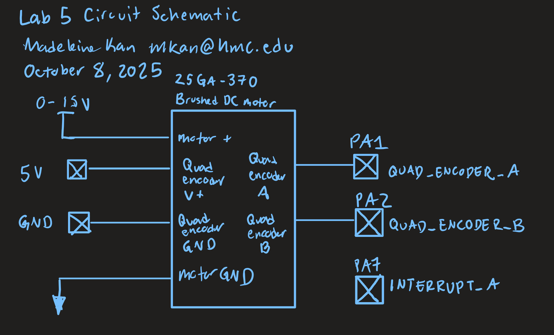
The purpose of this lab was to print out the speed of a brushed DC motor, in revolutions per second, based on interrupt signals from a quadrature encoder. These results were compared with the timing of using polling instead of interrupts.
Schematic
The circuit diagram is as follows:
A flow chart describing the flow of the program is as follows: 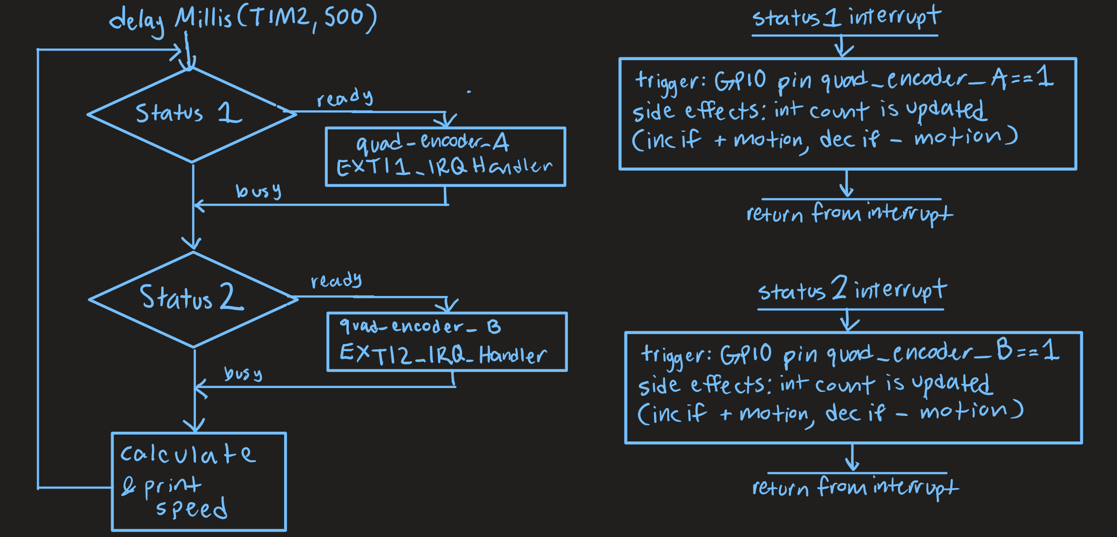
Calculations
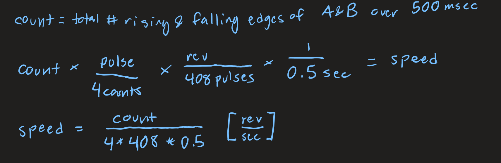
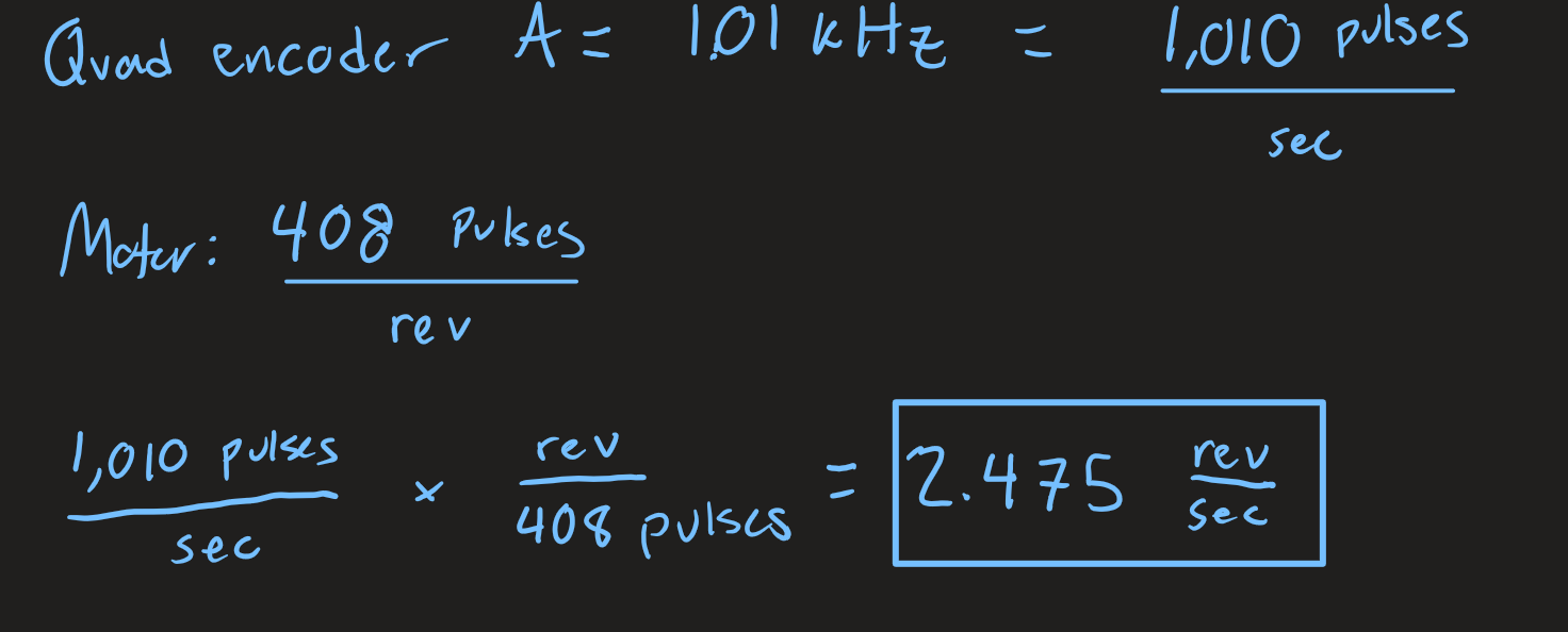
Motor speed as a function of count (an integer which was incremented on every rising and falling edge of both quadrature encoders) was calcualted as follows:
Code:
main.c
// main.c
// reads quadrature encoder signals
// prints speed of motor in rotations per second
// Madeleine Kan
// mkan@hmc.edu
// 10/8/25

#include "main.h"

float count = 0;
int A;
int B;

// Runs interrupt or polling version of main code
int main(void) {
    int interrupt = 1;
    if (interrupt == 1){
      motorInterrupt();
    } else {
      motorPoll();
    }
    return 0;

}

// Detects encoder pulses with interrupts
void motorInterrupt(void){
  // Enable quadrature encoder inputs
    gpioEnable(GPIO_PORT_A);
    pinMode(QUAD_ENCODER_A, GPIO_INPUT);
    pinMode(QUAD_ENCODER_B, GPIO_INPUT);
    GPIOA->PUPDR |= _VAL2FLD(GPIO_PUPDR_PUPD1, 0b01); // Set PA1 as pull-up
    GPIOA->PUPDR |= _VAL2FLD(GPIO_PUPDR_PUPD2, 0b01); // Set PA2 as pull-up

    // Enable PA7 as a flag for quadtrature encoder A
    pinMode(INTERRUPT_A, GPIO_OUTPUT);
    digitalWrite(INTERRUPT_A, 0);

    // Initialize timer
    RCC->APB1ENR1 |= RCC_APB1ENR1_TIM2EN;
    initTIM(DELAY_TIM);

    // 1. Enable SYSCFG clock domain in RCC
    RCC->APB2ENR |= RCC_APB2ENR_SYSCFGEN;
    // 2. Configure EXTICR for the input quadrature encoder interrupts PA1 and PA2
    SYSCFG->EXTICR[0] |= _VAL2FLD(SYSCFG_EXTICR1_EXTI1, 0b000);
    SYSCFG->EXTICR[0] |= _VAL2FLD(SYSCFG_EXTICR1_EXTI2, 0b000);

    // Enable interrupts globally
    __enable_irq();

    // Configure interrupt for rising and falling edge of GPIO pin for quadrature encoders
    // 1. Configure mask bit
    EXTI->IMR1 |= (1 << gpioPinOffset(QUAD_ENCODER_A));
    EXTI->IMR1 |= (1 << gpioPinOffset(QUAD_ENCODER_B));
    // 2. Enable rising edge trigger
    EXTI->RTSR1 |= (1 << gpioPinOffset(QUAD_ENCODER_A));
    EXTI->RTSR1 |= (1 << gpioPinOffset(QUAD_ENCODER_B));
    // 3. Enable falling edge trigger
    EXTI->FTSR1 |= (1 << gpioPinOffset(QUAD_ENCODER_A));
    EXTI->FTSR1 |= (1 << gpioPinOffset(QUAD_ENCODER_B));
    // 4. Turn on EXTI interrupts in NVIC_ISER
    NVIC->ISER[0] |= (1 << EXTI1_IRQn);
    NVIC->ISER[0] |= (1 << EXTI2_IRQn);

    while(1){
        delay_millis(TIM2, 500);
        float speed = count / (4 * 0.5 * 408);
        printf("motor speed: %f rev/s \n", speed);
        count = 0;
    }
}

// Quad encoder A interrupt handler
void EXTI1_IRQHandler(void){
    // Check that quad_encoder_a was what triggered our interrupt
    A = digitalRead(gpioPinOffset(QUAD_ENCODER_A));
    B = digitalRead(gpioPinOffset(QUAD_ENCODER_B));
    if (EXTI->PR1 & (1 << gpioPinOffset(QUAD_ENCODER_A))){
        // If so, clear the interrupt (NB: Write 1 to reset.)
        EXTI->PR1 |= (1 << gpioPinOffset(QUAD_ENCODER_A));
        if (A != B){ // B lags after A
          count++;
        } else { // A lags after B
          count--;
        }
        togglePin(INTERRUPT_A);
    }
}

// Quad encoder B interrupt handler
void EXTI2_IRQHandler(void){
    // Check that quad_encoder_b was what triggered our interrupt
    A = digitalRead(gpioPinOffset(QUAD_ENCODER_A));
    B = digitalRead(gpioPinOffset(QUAD_ENCODER_B));
    if (EXTI->PR1 & (1 << gpioPinOffset(QUAD_ENCODER_B))){
        // If so, clear the interrupt (NB: Write 1 to reset.)
        EXTI->PR1 |= (1 << gpioPinOffset(QUAD_ENCODER_B));
        if (B == A){ // B lags after A
          count++;
        } else { // A lags after B
          count--;
        }
        //togglePin(LED_PIN);

    }
}

// Detects encoder pulses with polling
void motorPoll(void){
    // Polling
    int volatile curA = digitalRead(QUAD_ENCODER_A);
    int volatile curB = digitalRead(QUAD_ENCODER_B);
    int volatile prevA = curA;
    int volatile prevB = curB;
    uint32_t ms = 500;

    // Enable quadrature encoder inputs
    gpioEnable(GPIO_PORT_A);
    pinMode(QUAD_ENCODER_A, GPIO_INPUT);
    pinMode(QUAD_ENCODER_B, GPIO_INPUT);
    GPIOA->PUPDR |= _VAL2FLD(GPIO_PUPDR_PUPD1, 0b01); // Set PA1 as pull-up
    GPIOA->PUPDR |= _VAL2FLD(GPIO_PUPDR_PUPD2, 0b01); // Set PA2 as pull-up

    // Enable PA7 as a flag for quadtrature encoder A
    pinMode(INTERRUPT_A, GPIO_OUTPUT);
    digitalWrite(INTERRUPT_A, 0);

    // Initialize timer
    RCC->APB1ENR1 |= RCC_APB1ENR1_TIM2EN;
    initTIM(DELAY_TIM);

    // 1. Enable SYSCFG clock domain in RCC
    RCC->APB2ENR |= RCC_APB2ENR_SYSCFGEN;
    // 2. Configure EXTICR for the input quadrature encoder interrupts PA1 and PA2
    SYSCFG->EXTICR[0] |= _VAL2FLD(SYSCFG_EXTICR1_EXTI1, 0b000);
    SYSCFG->EXTICR[0] |= _VAL2FLD(SYSCFG_EXTICR1_EXTI2, 0b000);

    // A lot of this code is adapted from delay_millis
    // so that polling can be executed within the while loop
    while(1){
      DELAY_TIM->ARR = ms;// Set timer max count
      DELAY_TIM->EGR |= 1;     // Force update
      DELAY_TIM->SR &= ~(0x1); // Clear UIF
      DELAY_TIM->CNT = 0;      // Reset count
      while(!(DELAY_TIM->SR & 1)){ // Wait for UIF to go high
        prevA = curA;
        prevB = curB;
        curA = digitalRead(QUAD_ENCODER_A);
        curB = digitalRead(QUAD_ENCODER_B);
        if (prevA != curA) { // A changes
          if (curA != curB){ // B lag behind A
            count++;
          } else {
            count--;
          }
          togglePin(INTERRUPT_A);
        } else if (prevB != curB) { // B changes
            if (curA == curB) { // B lag behind A
              count++;
            } else {
              count --;
            }
        }
      }
      float speed = count / (4 * 0.5 * 408);
      printf("motor speed: %f rev/s \n", speed);
      count = 0;
    }
}
Accompanying header file, main.h:
// main.h
// Madeleine Kan
// mkan@hmc.edu
// 10/8/25

#ifndef MAIN_H
#define MAIN_H

#include "STM32L432KC.h"
#include <stm32l432xx.h>

#define LED_PIN PB3
#define BUTTON_PIN PA4
#define QUAD_ENCODER_A PA1
#define INTERRUPT_A PA7
#define QUAD_ENCODER_B PA2
#define DELAY_TIM TIM2

#endif // MAIN_H

void motorInterrupt(void);
void motorPoll(void);
Results
The lab worked as expected! The MCU catches all signals at a high frequency, outputs a non-zero speed at low frequency, and a 0 speed when the motor is not powered. When the polarity of the power supplied to the motor is flipped, the sign of the output speed is also flipped. At ~10V, the script printed out a speed of 2.49 rev/sec. I verified this speed by counting how many revolutions the motor made over a minute (using cookie clicker). I got 149 revolutions over 60 seconds, which corresponds to a speed of 2.48 rev/sec.
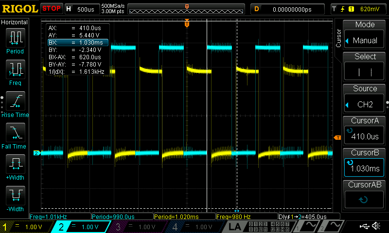
The oscilloscope trace below shows the signal from quadrature encoder A (in blue) and the corresponding interrupt signal (in yellow).
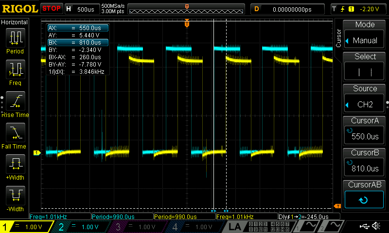
As shown in the distance between the vertical cursors, there is a delay between the encoder impulse and the interrupt signal of 260uS = 0.26 ms. Also, note that both signals have the same frequency of 1.01kHz. Based on this, I calculated the actual speed based on quad encoder A frequency. This resulted in an actual speed of 2.48 rev/sec, which is within 0.5% of the value of 2.49% calculated by the MCU.
I then ran the script using polling, and obtained the following oscilloscope trace showing the same signal from quadrature encoder A (in blue) and the corresponding polled signal (in blue).
As can be seen from the cursors, the delay between the encoder impulse and the polled signal of 620 uS = 0.62 ms, which is more than double the interrupt delay. Also, note that the encoder impulse has a frequency of 1.01 kHz, while the polled signal has a frequency of 980 Hz. Compare this to the lack of frequency delay observed in interrupts. This ocurrs due to the fact that interrupts handle code in hardware – when a trigger event happens, the MCU updates the program counter to point to the interrupt handler. This means, when the trigger event is not ocurring, the software experiences no delay from the interrupt handler. Any delays in interrupt handling are due to the length/intensity of the interrupt handler script. Polling, on the other hand, relies on software to repeatedly check for any trigger events. This inherently limits the frequency at which polling can occur. Investigating this further, I wrote a script that toggles a GPIO pin in a while loop with no trigger or hardcoded delay. This yielded a square wave captured in the following oscilloscope trace:
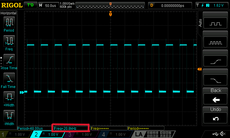
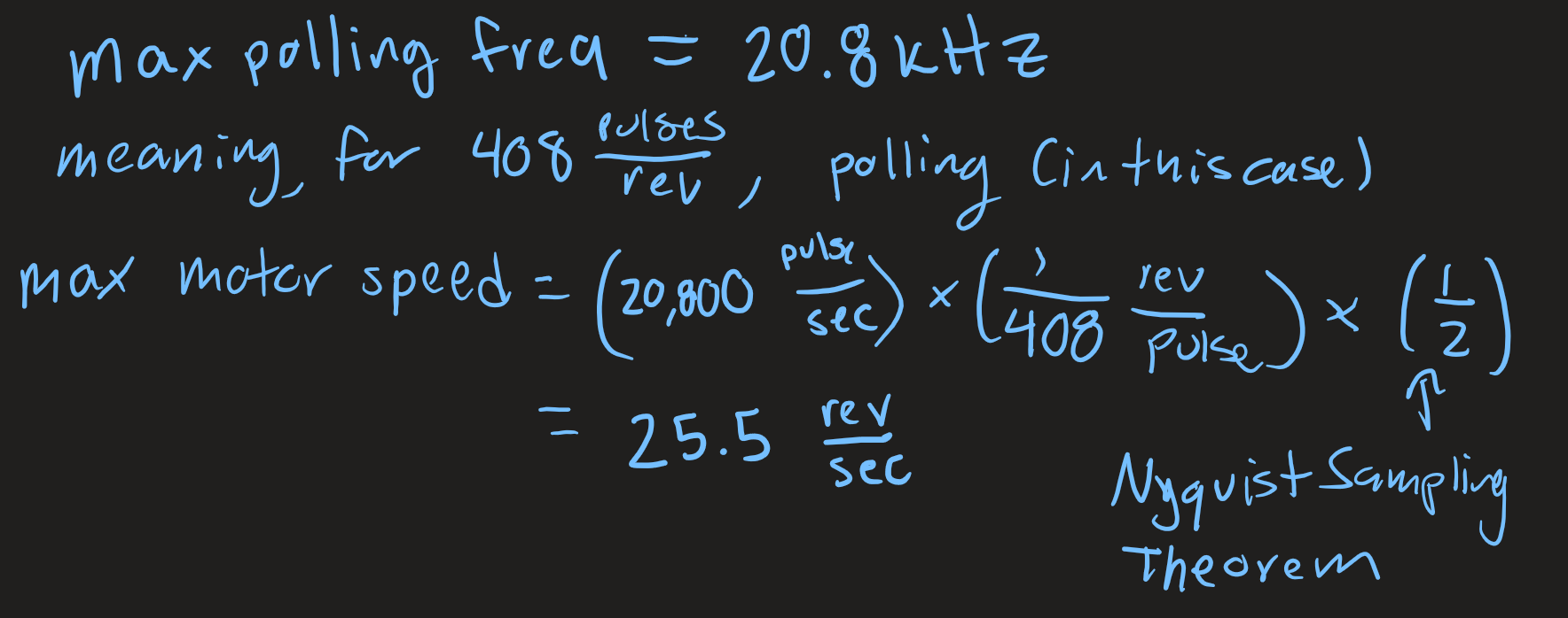
The maximum possible polling frequency is 20.8 kHz. From this, we can calculate the max speed that polling can accurately sample according to Nyquist’s sampling theorem.
Summary
I have spent ~10 hours on this lab. during this process, I learned a lot about interrupts, their advantage over polling, and quadrature encoders! It was really exciting to concretely compare the timing of the two methods. Additionally, I had fun developing a script to do something that felt tangible, and useful! Also, my classmates were super kind and helpful, which I really appreciated.
AI Reflection
For this week’s AI Refleciton, I asked ChatGPT to “Write me interrupt handlers to interface with a quadrature encoder. I’m using the STM32L432KC, what pins should I connect the encoder to in order to allow it to easily trigger the interrupts?”. Initially, the code it gave me had a few typos. To get the code to compile, I had to change APB1ENR to APB1ENR1 and RCC_APB1ENR_TIM2EN to RCC_APB1ENR1_TIM2EN. Once the code compiled, I added a print statement. However, nothing ended up printing. I think the timer was not fully configured (e.g. some necessary reegisters were not enabled). Besides this, I think the code that chatGPT produced was not super organized. While it did a good job of demonstrating the core functionality of the code, it used very few helper functions, and it wasn’t super readable. For instance, there was some raw timer bit manipulation in the TIM2_IRQ function, which was hard to interpret. That being said, the comments were useful! Below is the copy of the code that ChatGPT produced that I then modified:
#include "main.h"

int main(void){
  // Configure PA0 and PA1 as alternate function (AF mode) for Timer
  GPIOA->MODER &= ~(GPIO_MODER_MODE0_Msk | GPIO_MODER_MODE1_Msk); // Clear PA0 and PA1 mode
  GPIOA->MODER |= (GPIO_MODER_MODE0_1 | GPIO_MODER_MODE1_1); // Set PA0 and PA1 to alternate function
  GPIOA->AFR[0] |= (0x2 << GPIO_AFRL_AFSEL0_Pos); // Set AF2 for PA0 (TIM2_CH1)
  GPIOA->AFR[0] |= (0x2 << GPIO_AFRL_AFSEL1_Pos); // Set AF2 for PA1 (TIM2_CH2)

  // Enable the TIM2 clock
  RCC->APB1ENR1 |= RCC_APB1ENR1_TIM2EN;

  // Configure TIM2 in Encoder Mode
  TIM2->PSC = 0;  // Prescaler (no division)
  TIM2->ARR = 0xFFFF;  // Auto-reload register (max count)
  TIM2->CR1 = TIM_CR1_CEN;  // Enable the timer

  // Set the encoder mode (e.g., Encoder mode 1: Count rising edges of encoder signals)
  TIM2->SMCR = (TIM_SMCR_SMS_0 | TIM_SMCR_SMS_1);  // Encoder Mode 1 (TI1 + TI2)

  TIM2->DIER |= TIM_DIER_UIE;  // Enable update interrupt (overflow interrupt)

  // Enable NVIC for TIM2 interrupt
  NVIC_EnableIRQ(TIM2_IRQn);

}

void TIM2_IRQHandler(void) {
    if (TIM2->SR & TIM_SR_UIF) {  // Check if interrupt was caused by update event (overflow)
        TIM2->SR &= ~TIM_SR_UIF;  // Clear the interrupt flag
        // Handle your encoder position change here
        uint32_t encoder_position = TIM2->CNT;  // Read the counter value
        // Example: Print or process the encoder position
        printf("encoder position: %d", encoder_position);
    }
}